
FIELD NOTES / DOUBLE CURVATURE
Thermal Movement on Curved Aluminum Facades
How much a curved aluminum facade grows and shrinks with temperature — and how to allow for it in joints, brackets and the panel schedule.
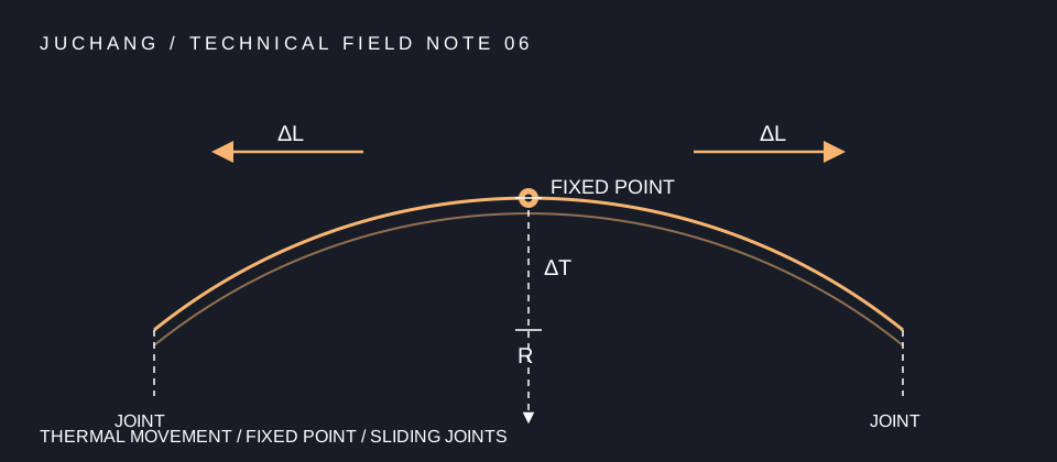
Aluminum moves more than the frame it hangs on
Aluminum is a lively material in the sun. Its linear coefficient of thermal expansion is about 23 millionths of a metre per metre per degree Celsius — roughly twice that of structural steel, which sits near 12. That single number is the whole story of thermal movement: every metre of panel grows by about 23 micrometres for each degree the metal warms, and shrinks by the same amount when it cools. The formula is short, ΔL = α × L × ΔT, and there is nowhere to hide from it. A facade that ignores the arithmetic does not stop the movement; it just absorbs it in the wrong places — in bowed faces, in sealant that has torn, or in fixings that have worked loose.
Run the numbers for the panels this site covers — solid aluminum sheet in 2.0, 2.5 and 3.0 mm, in 1100 or 3003 alloy in H24 temper, up to 1300 by 4000 mm. A single 4000 mm panel through a 50-degree seasonal swing grows by about 4.6 mm. That is the movement of one panel. A facade is not one panel: a 20-metre run of panels, fixed end to end, would try to grow by about 23 mm if nothing were allowed to slide. 4.6 mm is easy to miss. 23 mm is not.
The temperature that matters is the temperature of the metal, not the air. A sunlit facade runs hotter than the weather report, and a dark PVDF, powder or roller-coated face in direct sun runs hotter still — tens of degrees above the air on a still summer afternoon. The design temperature range therefore has to cover the surface temperature, not the shade temperature, and it is confirmed for the project rather than copied from a catalogue. The subframe adds a second mismatch: a steel support frame expands at about half the rate of the aluminum it carries, so every fixing sees the difference between the two materials as well as the movement of the panel itself.
On a curve, movement follows the arc
On a flat facade the direction of movement is obvious: along the panel. On a curved facade it follows the arc. A curved panel grows along its own curve, and as it grows the radius grows with it — by a small amount, but the same order of magnitude as the tolerances the facade is built to. Measure the movement along the developed arc length, not along the straight chord between the panel ends, or the allowance will be short exactly where the curve is tightest. The note on chord, arc length and rise on curved panel drawings sets out how those three dimensions relate, and the same care applies here: the arc is the length that changes.
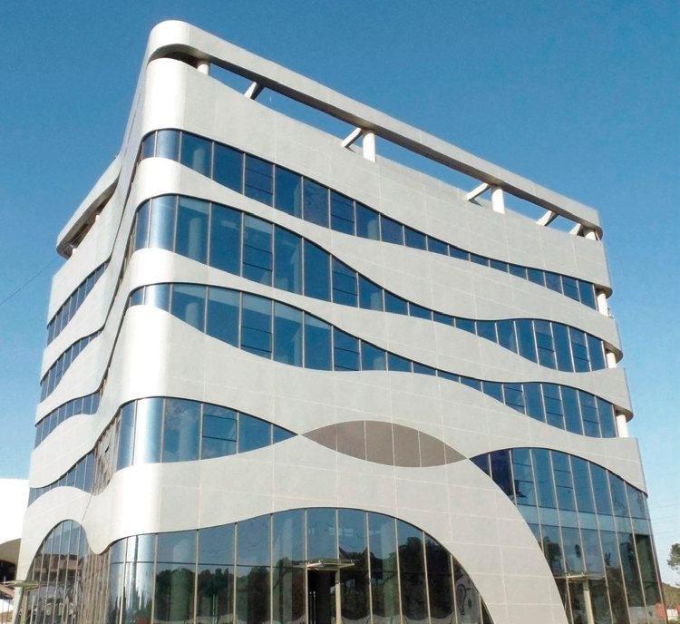
The shape of the surface decides where the movement goes. On a dome the panels grow outward from the crown in every direction, so the movement is radial and the joints around the crown take it up evenly. On a saddle the two principal curvatures pull in different directions, and the movement in one direction can be larger than in the other — the joint layout has to respect that, with the wider allowance where the longer arc runs. Where a panel changes from dome to saddle across its face, the movement changes direction mid-panel, and that is where a joint placed across the transition earns its keep.
Returns and folded edges complicate the picture. A stiff return restrains the edge of the panel, so the face between two returns takes up more of the movement than the edges do. Under daily temperature cycling that shows up as a faint bow — oil-canning — that comes and goes with the sun and is easy to mistake for a forming defect. It is not a defect in the forming; it is a restraint problem. Keep the returns as shallow as the design allows, or break the restraint with a relief in the return, and confirm the detail with the fabricator before the shop drawings are released.
One fixed point, the rest slide
The fixing rule is simple to state and worth enforcing: one fixed point per panel, and everything else slides. The fixed bracket pins the panel at one place; every other bracket carries a slotted hole or a sliding clip that lets the panel grow away from the fixed point. Put the fixed point near the middle of a run and the movement splits in both directions, halving the travel each joint has to absorb. Fix both ends of a long run and the panel has nowhere to go — it will bow, or it will force the fixings, and one of the two will give.
Movement accumulates away from the fixed point, so the bracket farthest from it needs the longest slot. Size each slot from the distance to the fixed point, the design temperature range and the panel length, then add the fabrication and installation tolerance on top — the slot is not the place to spend the tolerance budget. Check the slot at both ends of the temperature range: at the coldest design temperature the fixing must not sit against the end of the slot, and at the hottest it must not run out of travel either. A slot that is long enough on paper and installed with the bolt already at one end is a fixed point in disguise.
Bolts deserve a line of their own. A sliding connection only slides if the bolt is free to move in the slot, which means the clamping force has to be controlled — over-tightened, the bracket grips the panel and the joint stops working, and the movement reappears as a bowed face or a cracked coating. State the tightening instruction on the shop drawing, not in a site instruction that arrives after the first panels are up. The guide to subframe coordination for curved aluminum panels explains how the bracket layout and the support survey fit together, and the notes on offsetting a curved skin to locate brackets show how the bracket position is set from the finished face.
Size the joint for the hottest day, not the drawing day
A joint is a gap with a job to do, and the job changes with the temperature. In the heat the panels grow toward each other and the gap closes; in the cold they shrink apart and the gap opens. The gap that looks right on the day of installation is right only for that day's temperature. Size the joint from the design extremes instead: work out the gap at the hottest and the coldest design temperature, and set the installed gap from the temperature on the day the panel goes up. A gap table that lists the installed width against the installation temperature is a one-page document that prevents most joint arguments.
Record the installation temperature in the panel schedule, next to the panel ID. Without it, a joint measured on a cold morning cannot be judged — a wide gap in January may be exactly right, and the same gap in July is a failure. Measure the gap with a gauge, not by eye, and measure it in the local panel plane: on a curved surface the joint width measured from the front is not the width in the plane of the panels, and the difference matters where the curve is tight. The guide to joint width along a double-curved surface explains how to measure it so the number means something.
Where the joint is sealed, the sealant has to survive the same movement. A sealant's movement capability is stated by its manufacturer as a percentage of the joint width, and the joint has to be wide enough that the calculated movement stays inside that capability at both temperature extremes — confirm it against the manufacturer's data for the product actually specified, per project. A joint that is too narrow for its sealant does not fail on day one; it fails after a few seasons of cycling, when the sealant has torn and water has found the gap. Check the narrowest joint on the facade, not the average one: on a curved run the tightest point governs.
What to check on site
None of this is proved on paper. Build the joint and the bracket detail into the mock-up at full scale, with the real panel thickness, the real coating and the real fixings, and check the gap and the slot travel against the temperature on the day — then work out what the same joint will look like at the design extremes. If the project allows it, measure the mock-up again in different weather and compare. The notes on what to include in a curved cladding mock-up list the hard conditions a mock-up should represent; a thermal joint is one of them.
On site, the checks are quick and worth doing while the panels are still going up. Measure a sample of joints with a gauge and write the temperature next to the reading. Look at the brackets: a fixing that has travelled to the end of its slot is a warning that the fixed point is in the wrong place or the slot is too short. Look at the faces in raking light on a hot afternoon: a bow that appears with the sun and disappears by evening is movement looking for somewhere to go, not a forming fault.
The symptoms of a facade that was not allowed to move are consistent enough to recognise. Sealant that has split or pulled away from one side of a joint. Joints that have closed solid, with the panel edges touching or the coating rubbed bright where they meet. Faces that bow in the heat and flatten at night. Fixings that have elongated their holes or worked loose. Any one of these on a new facade is a reason to stop and check the fixing and joint logic before more panels go up.
A short checklist before release
State the design temperature range. Surface temperature, not air temperature, confirmed for the project.
Fix one point per panel. Everything else slides, with slots sized from the distance to the fixed point plus tolerance.
Size joints from the extremes. Set the installed gap from the installation temperature and record it in the schedule.
Check the tightest joint. Measure in the local panel plane; the narrowest point governs the sealant.
Prove it on the mock-up. Full-scale joint and bracket, measured at installation temperature and checked against the extremes.
Technical references
The source lists general material data: aluminum about 23 × 10⁻⁶ per °C, aluminum alloys 21–24. Confirm product-specific values and project requirements with the responsible design team.