
FIELD NOTES / DOUBLE CURVATURE
Minimum Bend Radius for Double-Curved Aluminum Panels
What sets the tightest curve a double-curved aluminum panel can take — alloy, temper, thickness, forming route — and how to state it on a drawing.
There is no single minimum radius
Every inquiry about double-curved panels eventually asks for one number: how tight can the curve go? The honest answer is that the minimum bend radius is not a property of the panel alone. It is the result of the alloy, the temper, the sheet thickness, the direction of the bend relative to the grain, the forming method, and whether the surface curves in one direction or two. Change any one of those and the achievable radius changes with it. A figure quoted without those conditions is not a specification; it is a starting point for a conversation with the fabricator, and the radius a project can actually use is confirmed against the drawing, not copied from a brochure.
That matters because the radius drives everything downstream. A radius that is too tight for the specified sheet shows up as cracking at the outer face, thinning at the bend, or a surface that will not hold its shape after forming. None of those failures is visible in a rendering. They appear at the press, or worse, after the panel is installed and the finish is on. The cheapest time to find the limit is before the shop drawings are released, when the radius is still a line on a drawing rather than a panel in a crate.
Grain direction deserves a line of its own. Sheet has a rolling direction, and a bend across the grain behaves differently from a bend along it. On a compound-curved panel the bend direction changes across the surface, so the tightest local radius may sit in the least forgiving orientation. Where a panel has one clearly critical curve, state the grain direction on the drawing and ask the fabricator to confirm the radius in that orientation. It is a small note that prevents a large argument later.
State the radius in a way the shop can measure
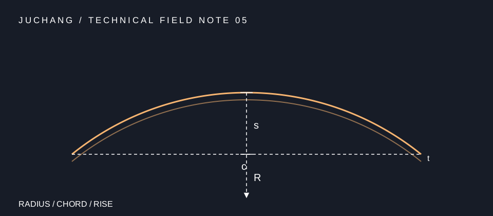
A radius dimension on its own leaves too much unsaid. State the chord and the rise alongside it, and say whether the radius is measured to the visible face, the back face or the neutral axis of the sheet. On a 3.0 mm sheet the difference between those references is small in absolute terms, but it is the same order of magnitude as the tolerance on a tight curve, so the shop needs to know which one governs. Give the direction of curvature too: a dome and a saddle can share a radius value and demand completely different forming. Where the surface is a true compound curve rather than a single arc, the radius is different in the two principal directions, so state both. The note on measuring a circular radius from chord and rise shows how those three dimensions relate on a drawing.
Put the tolerance next to the radius. A radius stated without a tolerance invites the shop to assume one, and the assumption is usually the loosest one. State how the radius will be checked — a radius template on site, a scan against the model, or a check against the approved sample — and who signs it off. The guide to specifying surface deviation on curved panels explains how to give that check a number to compare against, so the radius is verified rather than eyeballed.
Thickness and temper set the envelope
The panels this site covers are solid aluminum sheet in 2.0, 2.5 and 3.0 mm, in 1100 or 3003 alloy in H24 temper, up to 1300 by 4000 mm. Within that envelope the rule is simple to state and easy to get wrong in practice: thicker sheet needs a larger minimum radius, and a harder temper cracks sooner at a tight radius than a softer one. H24 is a strain-hardened temper, part-way between soft and full-hard, which is why it is a practical choice for formed cladding — but the exact radius it will accept still depends on the forming route and the direction of the bend, so the fabricator confirms the achievable radius for the specified alloy, temper and thickness on each project. Where a value is not confirmed for the project, it is not a specification yet.
Thickness also interacts with panel size. A tight radius on a large panel is a different forming problem from the same radius on a small one, because the sheet has to be controlled across its full width while it is being formed. Where a radius looks marginal, reducing the panel width or splitting the surface into smaller panels can bring it back inside what the sheet will do. The trade-off is more joints and more pieces, which is a design decision, not a fabrication failure — but it has to be made before the schedule is frozen, because it changes the panel count and the tooling.
Finish belongs in the same conversation. PVDF, powder and roller coatings are applied to the sheet, and a coating that is formed after application is worked hardest exactly where the radius is tightest. Ask the fabricator to confirm the coating sequence and whether the tightest radius on the project has been proven with the specified finish, rather than assuming a coating that survives a gentle curve will survive a tight one. A cracked coating at a bend is a finish failure that only shows up after forming, when the panel is already made.
The forming route changes the limit
A single-curved panel can be rolled. A double-curved panel cannot, at least not in one pass: the sheet has to be stretched or pressed into shape, and the route chosen changes both the minimum radius and the surface quality. Stretch forming holds the sheet at its edges and pulls it over a form, which suits smooth compound curvature but needs a form for each shape family. Press forming works the sheet in stages and suits tighter local curvature, at the cost of more handling and a greater risk of marking the visible face. The comparison of forming routes for double-curved panels sets out when each route fits and what it costs in tooling.
Whatever the route, a trial panel is the only proof that counts. A sample formed from the specified alloy, temper and thickness, at the tightest radius on the project, shows whether the surface holds, whether the finish survives forming, and whether the radius can be repeated across the panel family. Agree the trial before production, keep it as the reference sample, and write the agreed radius into the shop drawing revision so it cannot drift later. Photograph the trial from the same viewing distance and angle as the finished facade will be seen from, so the design team judges the surface the way a passer-by will. If the trial fails, the radius is renegotiated while the design can still absorb the change.
When the radius is too tight
Sometimes the honest answer is that the radius cannot be made as drawn. That is not the end of the design — it is the point where the design is adjusted with full information. The usual options are to relax the radius, split the surface into smaller panels, change the panel width so the forming route can control the sheet, or use a faceted transition for the tightest part of the surface. Each option changes the appearance at the joints, so the choice belongs to the design team, with the fabricator stating what each option costs in tooling and pieces. The notes on choosing panel width on a freeform facade and on faceted alternatives for compound-curved facades cover two of those options in detail.
What should not happen is a quiet substitution: a panel made flatter than drawn, or split into segments that were never shown on the elevation. Either one changes the reflected light across the facade, which is the first thing anyone notices on a curved building. If the radius has to change, change the drawing, issue a new revision, and list the affected panel IDs so the schedule, the mock-up and the site team all work from the same geometry.
Record the agreed radius where the site team will actually see it: in the panel schedule, against each affected panel ID, and on the mock-up sign-off sheet. A radius that lives only in an email thread will be missed by the person cutting the sheet. The schedule is the document that travels from the office to the factory floor, so the radius, the tolerance and the check method belong in it next to the finish and the quantity.
A short checklist before release
State the full geometry. Radius, chord, rise, direction of curvature and the reference face, all on the same drawing.
State the material. Alloy, temper and nominal thickness for the panels that carry the tightest radius.
Ask for the radius in writing. The fabricator confirms the achievable minimum for that material and forming route before the shop drawings are released.
Prove it with a trial. One sample at the tightest radius, in the specified finish, kept as the reference.
Record the agreement. The confirmed radius goes into the drawing revision, with the affected panel IDs listed.
Technical references
The source describes general engineering considerations. Confirm product-specific values and project requirements with the responsible design team.