
FIELD NOTES / DOUBLE CURVATURE
Double-Curved Aluminum Panel Drawings: What to Send for a Reliable Quote
The model, panel boundaries, sections and revision data needed to evaluate a compound-curved aluminum facade.
The rendering is a starting point
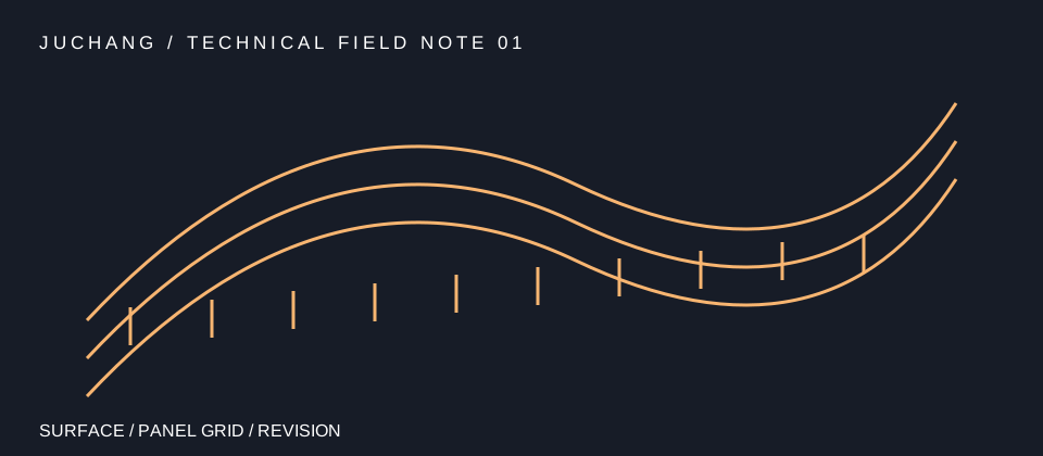
A rendering conveys the intended appearance, but it usually does not identify the exact surface, individual panel boundaries or fixing offsets. To evaluate fabrication, the supplier needs to know which parts are genuinely compound curved and which parts could be planar or single curved. A facade may have an overall double-curved silhouette while its skin is rationalized into easier panel families. The decision changes tooling, appearance at joints and potential cost.
Package the surface model and its reference frame
Provide the editable 3D surface model if available, along with the software and export format. STEP, IGES or Rhino 3DM are useful starting points when they preserve the intended geometry. State units, project datum, global coordinates and model revision. Include dimensioned plans and sections as PDF so the supplier can check scale and orientation. A mesh or image-only model may be useful for discussion, but it can require reconstruction before accurate forming and trimming are assessed.
Make each panel identifiable
Show panel boundaries and joints in the model or a coordinated elevation. Include a schedule with a unique panel ID, quantity, approximate bounding dimensions, facade zone, orientation, finish and drawing revision. Identify identical or mirrored pieces only where their geometry and fixing details really match. The panel schedule checker on this site detects missing entries and duplicate IDs in a CSV, but geometric equivalence still needs design review. Where panels meet glazing, parapets or another material, show the intended clearance and responsibility for the transition.
Document edges and attachment
Sections should show the visible face, returns, edge hem or welded detail, reinforcement, bracket positions and connection to the subframe. Call out drainage, movement allowance, access for installation and the expected viewing side. Specify which party engineers the supporting structure. Tooling and trial forming depend on alloy, temper, sheet thickness and curvature, so ask the fabricator to propose a forming route after reviewing the surface. Zahner describes how excessive forming can affect material quality, and panelization research treats reuse of molds as a cost variable.
Control the quote revision
Send one coordinated package with a dated index. If the surface changes, issue a new model revision and list changed panel IDs instead of quietly replacing a file. Ask the supplier to state the assumed panel count, unique shape count, forming or tooling allowance, sample requirement, finish specification, packing scope and destination. Request an exception list for any geometry that must be split or adjusted. A firm production commitment follows approved shop drawings and an agreed mock-up where the project requires one.
Technical references
- Zahner, Efficient Fabrication of Double Curved Surfaces ↗
- Eigensatz et al., Paneling Architectural Freeform Surfaces ↗
The sources describe general engineering considerations. Confirm product-specific values and project requirements with the responsible design team.